
Online map + grid as tile layer
New AFE grid system
Cell boundaries
Cell names
New AFE grid system
The Atlas Florae Europaeae (AFE) grid system was changed in 2000 (after AFE vols. 1 – 12) on the basis of the Paris 1998 meeting of the representatives of the atlas groups mapping the European vascular plants, mammals, birds, amphibians, reptiles, fungi and invertebrates. As before, the new grid system is modified from the Universal Transverse Mercator (UTM) co-ordinates and the Military Grid Reference System (MGRS), as defined in the official documents of the U.S. National Imagery and Mapping Agency (NIMA). The technical manuals of NIMA (Datums, Ellipsoids and Grid Reference Systems, TM 8358.1; The Universal Grids: Universal Transverse Mercator (UTM) and Universal Polar Stereographic (UPS), TM 8358.2) defining these systems are available as html and pdf documents at the web server of NIMA. The grid system of AFE is based on the World Geodetic System 1984 (WGS84) datum.
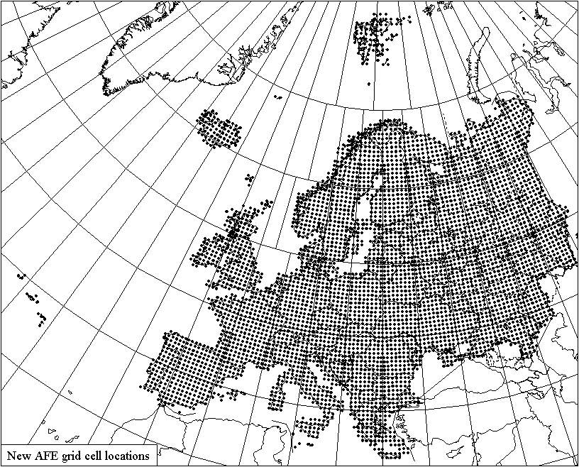
Fig. 1: The AFE grid cells with land in Europe.
Cell boundaries
The grid cells are bounded either by the “full” 50-km lines of the UTM (exclusively so in Albania, Baleares, Sardinia, Sicily, Slovenia and Turkey) or also by the boundaries of the MGRS zones. The deviations in the limits of UTM and MGRS are taken into account so that in the North Sea and in band X the grid cell boundaries are based on MGRS. Unlike before, the grid extends over terrestrial and marine areas following a regular pattern, without any deviations for coasts, islands, peninsulas, mountains, towns etc. There are c. 4750 cells with at least some land in Europe as delimited in AFE. In the old grid system there were 4419 grid cells.
Fig. 2: The UTM 50 km gridlines of zones 34 (21° – 24° E), 35 (24° – 30°E E) and 36 (30° – 36° E) in Finland.
Fig. 3: The pattern of merging the slices into the AFE grid cells.
Projection: UTM 35N. – Note the narrow slices cut by the zone boundaries (left). Depending on the width of the southern edge, the slices bounded by zone boundaries treated as independent cells (width 33.3 – 50 km), merged with a similar slice on the other side of the zone boundary (width 16.7 – 33.3 km), or joined to the adjacent cell in the same zone (width < 16.7 km).
Became the meridian convergence the UTM / MGRS zones are narrower towards the north. The basic rules for merging the slices smaller than 50 x 50 km with the other slices are:
- if the “base width” (in the northern hemisphere, width of the southern edge of the slice) of the slice is over 33.3 km, then the slice is treated as an independent grid cell,
- if the “base width” is between 16.7 and 33.3 km, then the slice is joined with the similar adjacent slice
- if the “base width” is less than 16.7 km, then the slice is joined to the adjacent 50 x 50 km slice.
This pattern is followed in all normal 6 degree wide UTM zones (1-30, 38-60) for the small zone boundary so that:
- Slices with their southern margin at 0 – 350000 m, 2900000 – 3500000, 4650000 – 5050000, 5950000 – 6250000, 7050000 – 7350000, 8100.000 – 8350000 and 9050.000 – 9300.000 m N are treated as independent cells.
- Slices with their southern margin at 2100000 – 2850000, 4150000 – 4600000, 5550000 – 5900000, 6700000 – 7000000, 7750000 – 8050000, 8750000 – 9000000 m N are joined to the adjacent full 50 x 50 km quadrant in the same zone. If the slice is at the W boundary of the MGRS zone, it is joined to the quadrant east of it. Similarly, at the E margin of a MGRS zone boundary, the slice is joined to the quadrant west of it.
- Slices with their southern margin at 400000 – 2050000, 3550000 – 4100000, 5100000 – 5500000, 6300000 – 6650000, 7400000 – 7700000, 8400000 – 8700000 m N are joined with a similar slice in the neighbouring MGRS zone.
Exceptions to the above rules are caused by the differences between the UTM and MGRS zones:
- Zones 31 and 32 between 56° and 64° N. The central meridian of the MGRS zone 31 is at 3°E, which in this area is also the boundary between the zones 31 and 32. The normal merging pattern cannot be followed here, because the grid lines of these zones do not cross each other symmetrically at the zone boundary. The southeasternmost grid cells of 31W are extended southwards to the 7100000 m northing in zone 32, and the northeasternmost cells of 31U are cut by the northing of 6200000 m of zone 32. Between 6200000 and 7100000 m the westernmost cells of zone 32 are merged using the typical 16.7 / 33.3 km rule, although this here results in cells of unique and shape. However, this concerns only marine areas.
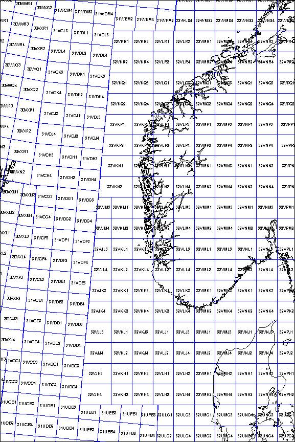
Fig. 4: The AFE grid cells boundaries in the North Sea and surroundings.
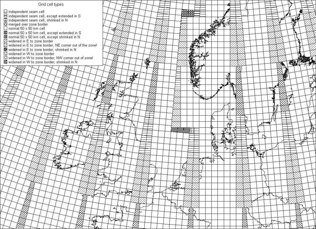
Fig. 5: The AFE grid cell boundaries and cell types in the North Sea and surroundings.
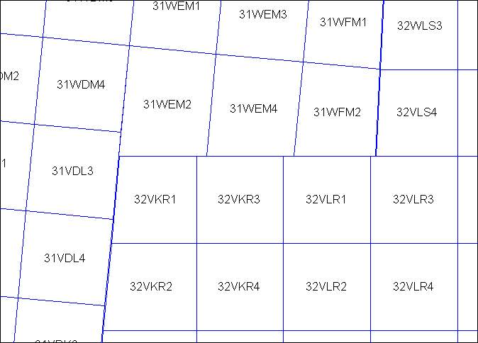
Fig. 6: The AFE grid cell boundaries at the 32V / 31W area.
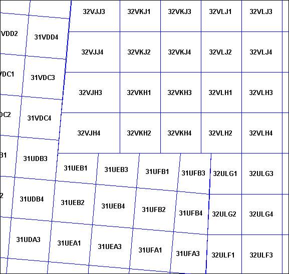
Fig. 7: The AFE grid cell boundaries at the 32V / 31U area.
- Band X. At the boundaries of MGRS zones 31 / 33, 33 / 35 and 35 / 37 above 72° N the merging pattern is different because here the longitudinal zones are wider than elsewhere:
- Slices with their southern margin at 8100000 – 8200000, 8600000 – 8700000, 9050000 – 9200000 m N are treated as independent cells.
- Slices with their southern margin at 8000000, 8050000, 8400000 – 8550000, 8900000 – 9000000 m N are joined to the adjacent full 50 x 50 km quadrant in the same zone. If the slice is at the W boundary of the MGRS zone, it is joined to the quadrant east of it. Similarly, at the E margin of a MGRS zone boundary, the slice is joined to the quadrant west of it.
- Slices with their southern margin at 8250000 – 8350000, 8750000 – 8850000, 9250000 – 9300000 m N are joined with a similar slice in the neighbouring MGRS zone.
- The northernmost cells of the MGRS zones 32, 34 and 36 (S boundary at 7.950.000 m N) are extended northwards so that their north boundary is at 8.000.000 m N of zones 31, 33, 35 and 37.

Fig. 8: The AFE grid cell boundaries at the northernmost part of 34W.
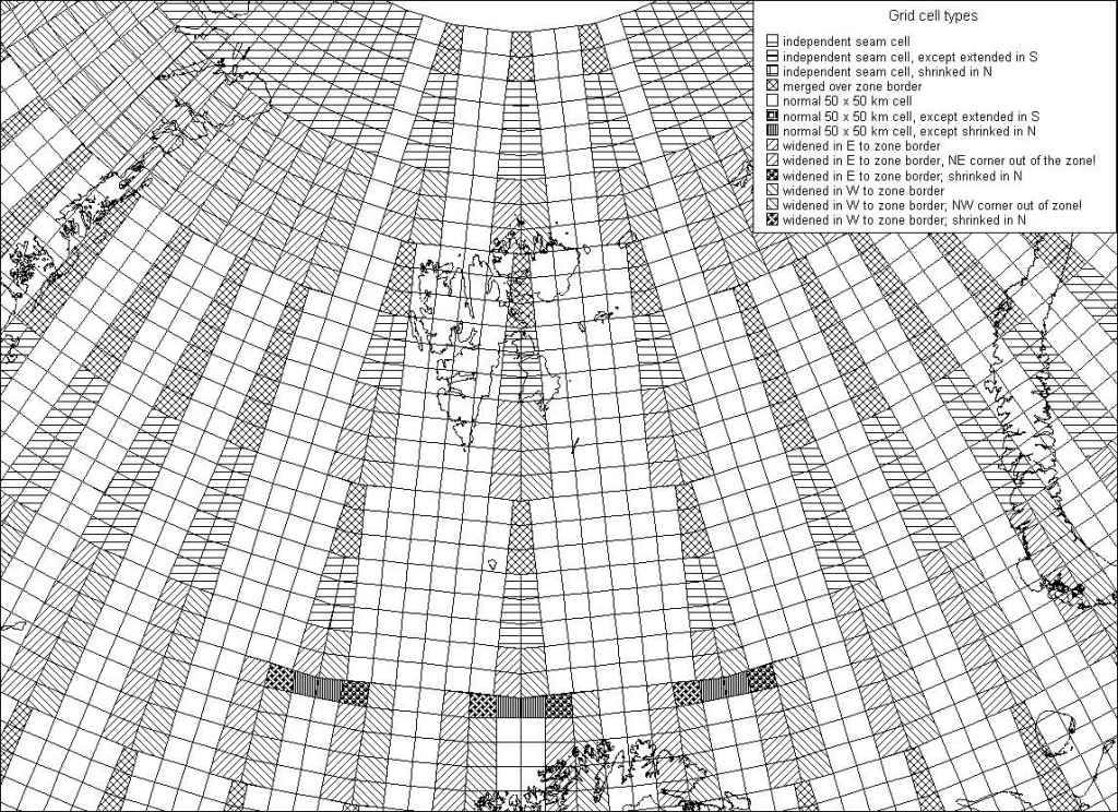
Fig. 9: The AFE grid cell boundaries and cell types in band X.
Cell names
The grid cell names (eg., 35VLH3) of the new grid consist of four elements:
- MGRS longitudinal zone number (e.g. “35”). Zone number for the point where the grid cell centroid is situated. For cells that in W – E direction cover parts of two MGRS zones and have their centroid exactly at the border of two zones, the number is taken from the western zone.
- MGRS latitudinal band letter (e.g. “V”). Based on the latitude of the grid cell centroid. In the northern hemisphere the grid cells that have their southern boundary at 850000, 1750000, 2650000, 3500000, 4400000, 5300000, 6200000, 7050000, 8000000 and (boundary to UPS area) 9.300.000 metres are cut by a latitudinal MGRS band boundary. If S edge is at 850000, 3500000, 4400000, 7950000 or 9300000 metres north, then the band letter is taken from the southern band, in the other cases from the northern band.
- MGRS 100 x 100 km square designator. A two-letter code (e.g., “LH”) for the 100 km square in which the cell centroid lies. For cells that in W – E direction cover parts of two MGRS zones and have their centroid exactly at the border of two zones, the code is taken from the western zone.
- 50 x 50 km quadrant designator. This is number 1, 2, 3 or 4 for the NW, SW, NE and SE quadrants of the 100 km x 100 km cell, and is based on the metric easting and northing of the grid cell centroid. This means that if the eastern margin grid cells of a MGRS zone have quadrant codes 1 and 2, the adjacent western marginal cells on the E side of the zone boundary will automatically have codes 3 and 4. Likewise, if the margin cells on the W side of the zone boundary have codes 3 and 4, the cells on the E side will have codes 1 and 2— This differs from the former Atlas Florae Europaeae grid naming system, where the E side cells also had codes 1 and 2 if there were no 3 and 4 quadrants on the W side of the zone margin.
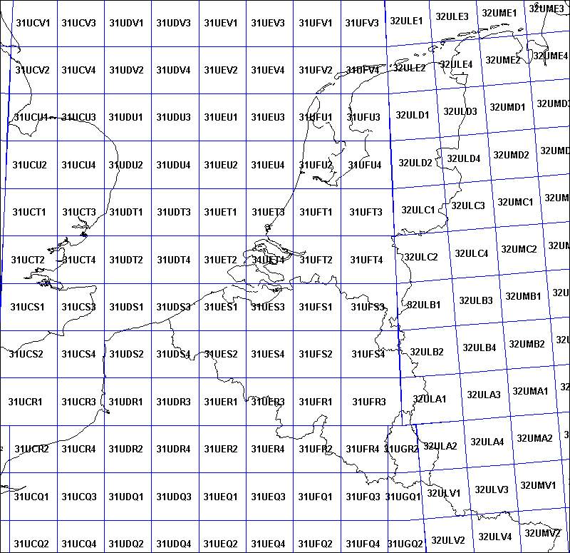
Fig. 10: An example of grid cell naming system.